Skip to content
Landscaping PeabodyMassachusetts

Homeowner Engineering & Construction Guide

How to Build a Retaining Wall: Planning, Key Steps & Common Mistakes

A retaining wall is a functional structural system that restrains lateral soil pressure, stabilizes slopes, and manages groundwater runoff. This educational guide explains the fundamental build sequence—from site evaluation and leveling pads to drainage physics and Massachusetts building code thresholds—so you understand what makes a retaining wall endure.
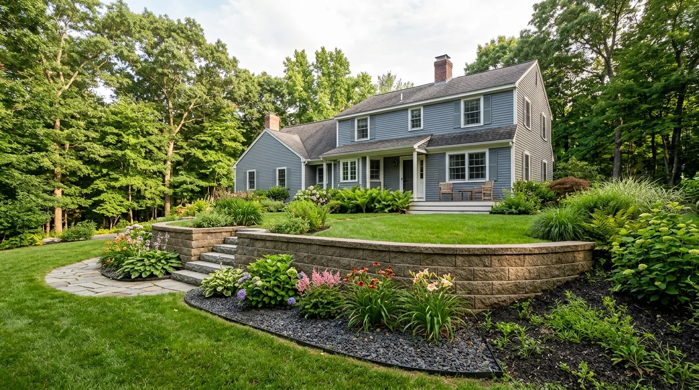
Low segmental concrete block retaining wall integrated into a terraced lawn and perennial garden in New England
A properly engineered segmental retaining wall creates stable usable terraces while relieving hydrostatic water pressure through a dedicated sub-surface drainage column.

Referral Service Disclosure: Landscaping Peabody MA is an independent homeowner referral service connecting property owners with licensed, independent landscaping and hardscaping professionals across the North Shore. We do not provide in-house contracting, engineering calculations, or direct construction services. All construction guidance presented here is for educational planning purposes; actual project specifications must adhere to the selected product manufacturer's instructions, Massachusetts building code, and site-specific engineered plans.

Quick Summary

How a Retaining Wall Is Built: The High-Level Sequence

Building a durable retaining wall involves ten core phases: assessing the site and calling Dig Safe (811), confirming building permits and engineering requirements, excavating a trench to solid subgrade, compacting a dense-graded crushed gravel leveling pad, precision-leveling the buried first course, stacking modular units with built-in setback, installing a clean crushed stone drainage column with a perforated pipe sloped to daylight, incorporating geogrid reinforcement where engineered, adhering cap stones, and grading surface runoff away from the wall.

Crucial Safety & Engineering Notice

Retaining walls are structural retaining elements, not decorative toys. Wall height, native soil conditions, steep slopes, groundwater seepage, and surcharges (such as driveways, swimming pools, or adjacent buildings) can instantly transform a routine yard improvement into a complex engineering challenge. Never rely on universal dimensions; always adhere to manufacturer installation tables, local building codes, and stamped plans prepared by a registered Professional Engineer (PE) when required.

Fundamental Distinction

Decorative Landscape Border vs. Structural Retaining Wall

Homeowners frequently confuse decorative landscape borders with retaining walls, but from an engineering and safety perspective, they perform entirely different tasks:

Decorative Landscape Border
  • Purpose: Separates mulch beds from lawn, contains topsoil, and creates visual definition.
  • Load: Holds minimal or zero lateral earth pressure (usually under 6 inches of uncompacted mulch).
  • Failure Risk: Cosmetic only; displaced units will not damage property or cause slope slides.
  • Read More: Explore our flower bed edging ideas guide.
Structural Retaining Wall
  • Purpose: Restrains significant active lateral soil pressure from elevated ground to create flat usable grade.
  • Load: Resists thousands of pounds of soil mass, groundwater hydrostatic pressure, and surcharge weights.
  • Failure Risk: Structural catastrophe; blowouts can destabilize foundations, collapse driveways, or cause landslides.
  • Services: Connect with local pros through our Peabody retaining wall service.

Treating a structural retaining wall as an oversized garden border is the leading cause of DIY wall blowouts. If the ground on one side of the wall is higher than the other, you are building a structural retaining system that must be planned accordingly.

Soil Mechanics & Physics

How Retaining Walls Work: Resisting Earth & Water Pressure

A retaining wall is constantly engaged in a physical battle against gravity and hydrology. Understanding these basic mechanical forces demystifies why seemingly minor construction steps (like base compaction and clean gravel backfill) are so vital:

1. Lateral Earth Pressure

Undisturbed soil naturally seeks its internal angle of repose (friction angle). When a vertical cut is made into a slope, the wedge of soil behind the cut wants to slide forward and downward along a natural shear plane. This generates active lateral earth pressure pushing against the back of the wall. The taller the wall, the exponentially larger this soil wedge becomes.

2. Hydrostatic Water Pressure

Dry soil is relatively predictable. However, when rainfall or snowmelt saturates backfill that lacks adequate drainage, trapped water fills the soil pores. Water weighs 62.4 lbs per cubic foot, while water-saturated soil can weigh 120 to 140 lbs per cubic foot. This creates hydrostatic pressure—a fluid hydraulic wedge that pushes relentlessly against the wall blocks. Water pressure is the culprit behind more than 80% of residential wall blowouts.

3. Structural Resistance Mechanisms

Retaining walls counteract these forces using one of two primary structural approaches:

  • Gravity Walls: Rely strictly on their own mass and backward setback angle (batter) to hold back the soil wedge. Practical for low walls (typically under 3 to 4 feet depending on block weight).
  • Reinforced (MSE) Walls: Mechanically Stabilized Earth systems use horizontal layers of geogrid mesh embedded into the soil behind the wall. The mesh interlocks with compacted stone, using the weight of the soil itself to anchor the wall facing.

Structural Anatomy

The Core Anatomy of a Segmental Retaining Wall

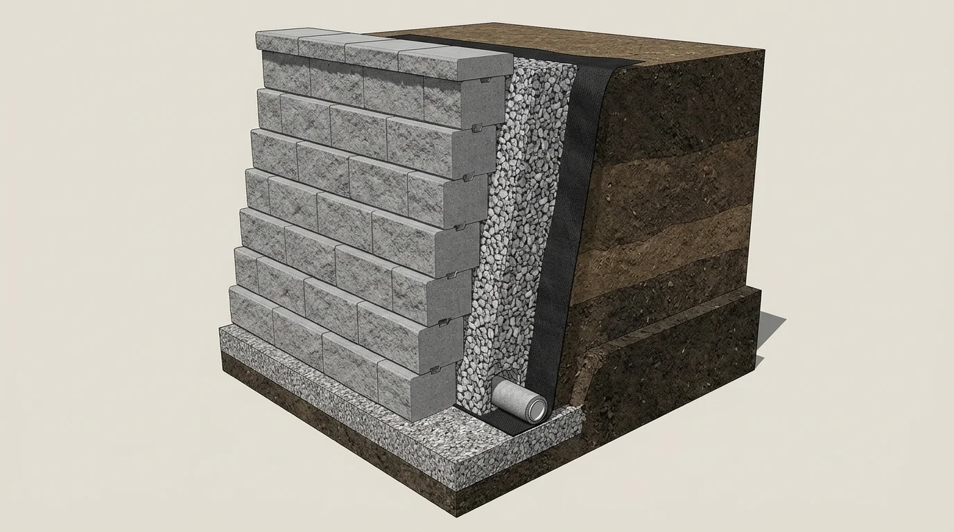
Every layer in a modular retaining wall serves a distinct engineering purpose. Examine the cutaway diagram below to understand how the components fit together.
Detailed 3D architectural cross-section cutaway showing the 10 structural layers of a segmental retaining wall
Cross-section diagram illustrating the relationship between the compacted leveling pad, buried base course, interlocking modular blocks, drainage aggregate column, perforated drain pipe, non-woven filter fabric, and compacted backfill soil.
1. Compacted Subgrade

The native mineral soil at the base of the excavated trench, compacted to support the entire structural weight without shifting or settling.

2. Granular Leveling Pad

Dense-graded crushed stone (minimum 6 inches thick), mechanically compacted to create a flat, unyielding foundation for the first course of blocks.

3. Buried Base Course

The bottom row of blocks, buried below finished grade to anchor the wall against lateral sliding (kick-out) at the toe.

4. Facing Units & Setback

Precast concrete blocks stacked with integrated lips or pins that lean each course slightly backward (batter) into the retained slope.

5. Crushed Stone Drainage Column

A minimum 12-inch column of clean, washed 3/4-inch angular crushed stone immediately behind the blocks to let water drop freely.

6. Perforated Drain Pipe

Perforated pipe resting at the bottom of the drainage gravel, sloped at a 1% minimum pitch to evacuate groundwater to daylight.

7. Geotextile Filter Fabric

Non-woven polypropylene fabric separating the clean drainage gravel from native infill soil to prevent fine silt from clogging the drainage zone.

8. Compacted Infill Backfill

Select granular or clean native soil placed behind the filter fabric and compacted in thin 6- to 8-inch lifts using mechanical compactors.

9. Universal Cap Units

Solid coping stones glued to the top course with high-strength exterior concrete adhesive to seal block cores and provide a clean finish.

10. Impervious Cap & Swale

A 6- to 8-inch cap of dense topsoil or clay graded away from the wall to prevent surface runoff from pouring directly into the drainage gravel.

Site Evaluation

Before You Build: Critical Factors to Evaluate

Before buying blocks or renting machinery, conduct a comprehensive site assessment. Any of the following physical factors can dramatically alter project complexity:

Total Retained Height

Measure the vertical difference from the bottom of the leveling trench to the top of the planned wall. Remember that local building codes regulate total height, not just the exposed face visible above ground.

Slope Geometry Above and Below

Is the ground above the wall flat, or does it slope steeply uphill? An uphill slope (e.g., 3:1 or 2:1 pitch) adds massive surcharge weight that pushes harder against the wall. Similarly, a slope dropping off below the toe requires a deeper buried base course to prevent the foundation from sliding out.

Surcharges (Vehicles, Structures, Patios)

A surcharge is any external load positioned in the soil mass behind the wall. Common surcharges include driveways, parked cars, detached garages, retaining walls stepped closely above, swimming pools, or heavy stone patios. Surcharges significantly increase lateral loads and routinely require engineered geogrid or concrete footings.

Property Lines & Municipal Setbacks

Walls cannot be built over property lines. Be aware that the foundation leveling pad and drainage excavation extend 12 to 24 inches behind and in front of the blocks. Verify property boundaries to ensure the entire excavation remains on your lot.

Underground Utilities (Call 811)

In Massachusetts, call Dig Safe (811) at least 72 hours prior to excavating. Excavating into buried gas, electrical, or fiber-optic lines carries severe safety risks and financial penalties under M.G.L. c. 82 § 40.

Building Code & Local Rules

Massachusetts & Peabody Retaining Wall Regulations

Retaining walls in the Commonwealth of Massachusetts are governed by the 10th Edition of the Massachusetts State Building Code (780 CMR):

Key Statutory & Code Requirements:

1. The 4-Foot Permit Exemption Threshold (780 CMR § 105.2)

A building permit is generally exempt for retaining walls that are not over 4 feet (1,219 mm) in height, measured from the bottom of the footing or leveling pad to the top of the wall.

Critical nuance: Height is measured from the bottom of the buried foundation, NOT from the visible ground surface! If a wall shows 3 feet of exposed block but has 14 inches of buried base and gravel pad, its structural height exceeds 4 feet and it is subject to permit requirements.

2. The Surcharge Rule (Eliminates Permit Exemption)

Regardless of height, ANY retaining wall supporting a surcharge—such as a driveway, parking area, building foundation, swimming pool, or steep hillside—requires a building permit and stamped engineering plans prepared by a Massachusetts-registered Professional Engineer (PE). A 2.5-foot wall holding up a driveway is NOT exempt from code review.

3. Pedestrian Guardrail Requirements (780 CMR § 1015)

Where retaining walls create an abrupt walking surface drop-off greater than 30 inches, building codes frequently mandate a code-compliant protective guardrail or fence (minimum 36 to 42 inches in height) to protect pedestrians from falling.

4. Local Peabody Municipal Jurisdiction

In Peabody, building permits are administered by the City of Peabody Inspectional Services Department located at 24 Lowell Street. Furthermore, if your property is within 100 feet of a wetland buffer zone (such as corridors near Proctor Brook, Crane Brook, or Goldthwaite Brook), the Peabody Conservation Commission must review the project under the Massachusetts Wetlands Protection Act (M.G.L. c. 131 § 40) before earth disturbance.

Note: Always confirm project-specific permit requirements with the City of Peabody Building Department before ordering materials. Do not guess on structural exemptions.

Step-by-Step Educational Sequence

The 10-Step Retaining Wall Build Sequence

Follow this educational overview to understand how professional hardscapers sequence a segmental retaining wall installation.
01Phase 01 of 10

Site Layout, Utility Marking & Property Boundary Review

Map the proposed wall alignment, verify property lines and municipal setbacks, and arrange underground utility marks before any tools touch the ground.

What Happens:

Homeowners or contractors mark the trench route with spray chalk, string lines, or wooden survey stakes. In Massachusetts, you must notify Dig Safe (811) at least 72 hours before excavating to locate underground gas, power, and telecommunication lines. Property boundaries must be confirmed to avoid encroaching on neighboring parcels.

Why It Matters:

Striking an unmarked electric or gas line presents immediate safety hazards and statutory liabilities under M.G.L. c. 82 § 40. Furthermore, building a structural wall across a property boundary can result in costly mandatory demolition orders.

What Can Go Wrong:

Severed irrigation lines, punctured utilities, or disputes with neighbors if wall foundations or backfill grading cross property lines.
Critical Caution: Always call 811 before digging. Dig Safe marks public utilities; private lines (pool wiring, septic feeds, landscape lighting) require separate manual verification.
02Phase 02 of 10

Code Verification, Permit Review & Engineering Evaluation

Verify whether your proposed wall height, slope, or surcharge triggers municipal building permits or structural engineering requirements.

What Happens:

Review the total planned height—measured from the bottom of the buried foundation leveling pad to the top of the wall cap. Check whether surcharges (driveways, vehicles, patios, or uphill slopes) act upon the wall. If total height exceeds 4 feet or if any surcharge exists, consult the local building department and engage a licensed engineer.

Why It Matters:

Under 780 CMR (Massachusetts State Building Code, 10th Edition), unpermitted construction of structural walls exceeding permit thresholds violates state law and invalidates home insurance coverage in the event of wall failure.

What Can Go Wrong:

Building a wall taller than 4 feet without engineering calculations or municipal permits, resulting in stop-work orders, fines, or catastrophic wall collapse.

Critical Caution: Confirm specific requirements with the City of Peabody Building Department at 24 Lowell Street or your local municipality before purchasing materials.
03Phase 03 of 10

Selecting the Retaining Wall System & Reviewing Manufacturer Specs

Choose an engineered modular system, natural stone, or timber assembly and obtain the manufacturer's exact technical installation guide.

What Happens:

Select a commercial segmental retaining wall (SRW) block system featuring integrated rear setback lips or fiberglass alignment pins. Obtain the manufacturer's technical specifications, which outline maximum gravity wall heights, minimum base depths, and geogrid reinforcement charts.

Why It Matters:

Every manufactured SRW system has distinct unit weights, setback angles (battering), and interlocking shear capacities. Generic installation techniques cannot substitute for manufacturer-tested engineering data.

What Can Go Wrong:

Mixing incompatible block types or exceeding a block's engineered gravity height limit without installing specified geogrid reinforcement.

Critical Caution: Never guess installation parameters. Follow the selected manufacturer's published installation manual for step-downs, corners, and curve radii.
04Phase 04 of 10

Trench Excavation to Stable Native Subgrade

Excavate the foundation trench deep and wide enough to accommodate the compacted gravel leveling pad and buried base course.

What Happens:

Dig a trench along the wall path. The trench must be wide enough to leave at least 6 inches of compacted gravel base in front of and behind the blocks, and deep enough to bury the manufacturer-specified leveling pad (typically 6 inches minimum) plus the buried base course (often 1 inch of buried block per 1 foot of wall height).

Why It Matters:

The entire weight of the wall and retained soil rests on this footprint. Excavating to undisturbed, unyielding native subgrade prevents localized settlement, tilting, and sinkholes.

What Can Go Wrong:

Placing the leveling pad over loose topsoil, organic matter, or muddy subgrade, leading to severe foundation settlement once backfilled.

Critical Caution: If soft organic soil, peat, or standing water is encountered at trench depth, excavate down to firm mineral soil and replace with compacted crushed stone.
05Phase 05 of 10

Installing & Compacting the Granular Leveling Pad

Install dense-graded crushed stone base material and mechanically compact it until completely rigid and level.

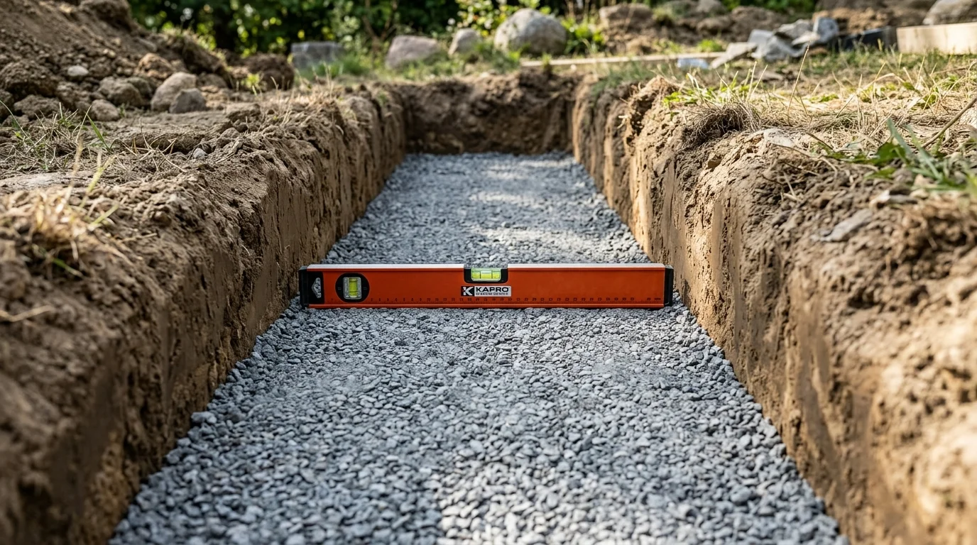
Compacted crushed stone leveling pad inside an excavated trench checked with a torpedo level
Step 5: The compacted crushed stone leveling pad must be checked continuously with a level. A flat, dense base is non-negotiable.
What Happens:

Spread dense-graded crushed stone (often 3/4-inch minus dense aggregate with fines) in 2- to 3-inch lifts. Mechanically compact each lift with a vibratory plate compactor. Check the pad continuously with a level and screed pipes to achieve a flat, dense, uniform surface.

Why It Matters:

A segmental retaining wall is a dry-stacked, flexible system. The crushed gravel leveling pad distributes the massive concentrated loads evenly across the subsoil and prevents frost movement.

What Can Go Wrong:

Using loose round pea gravel or uncompacted sand that shifts under the weight of the blocks, causing the foundation to sag unevenly.

Critical Caution: Do not use concrete sand or uncrushed pea stone as a leveling pad. Use angular dense-graded crushed aggregate compacted to at least 98% Standard Proctor density.
06Phase 06 of 10

Setting and Precision Leveling of the First Course

Place, align, and precision-level each base block front-to-back and side-to-side, burying it below finished grade.

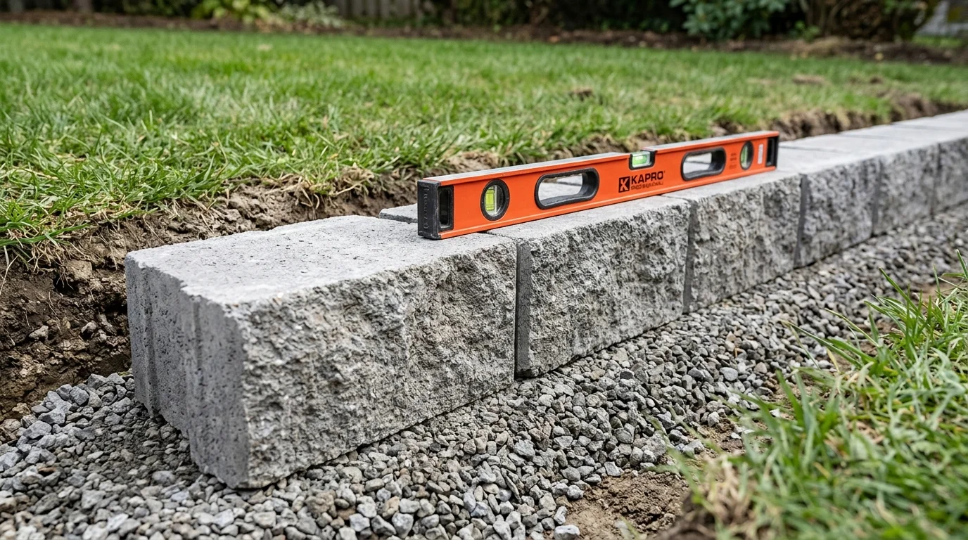
First course of split-face segmental concrete retaining blocks aligned and leveled on a crushed aggregate base
Step 6: Setting the first course. Every block must be leveled side-to-side and front-to-back, aligned to a string line, and buried below grade.
What Happens:

Set the first course of blocks directly on the compacted gravel pad. Knock down high spots with a dead-blow rubber mallet. Use a 2-foot or 4-foot torpedo level across adjacent units. Align the front faces against a tight string line.

Why It Matters:

This is the single most critical step in retaining wall construction. Every fraction of an inch that this first course is off-level will be exaggerated on subsequent courses as the wall rises.

What Can Go Wrong:

Rushing this step. If block #3 is 1/8 inch higher than block #2, by course 5 there will be severe gaps, rocking units, and misaligned pins.

Critical Caution: Check every individual block twice: level along the length and level from front to back. Never shim segmental blocks with wood or mortar.
07Phase 07 of 10

Stacking Subsequent Courses with Setback & Staggered Joints

Stack successive courses, staggering vertical joints by half a block and engaging setback lips or alignment pins.

What Happens:

Sweep the top of each course clean of all gravel and debris before placing the next tier. Stagger vertical joints in a running bond pattern (so joints never align vertically). Engage the rear lip or install alignment pins according to system design, establishing the required backward batter.

Why It Matters:

Battering (leaning the wall slightly backward into the slope, typically 3° to 10°) shifts the wall's center of gravity backward, counteracting the active lateral earth pressure of the retained soil.

What Can Go Wrong:

Aligning vertical joints, which creates continuous weak shear planes that allow blocks to separate under soil pressure.

Critical Caution: Keep the block tops swept clean. A single stray 1/4-inch pebble trapped between block tiers will throw the entire course out of level.
08Phase 08 of 10

Installing the Drainage Aggregate Column, Pipe & Filter Fabric

Place perforated drain pipe at the base, column clean crushed stone behind the units, and wrap with non-woven filter fabric.

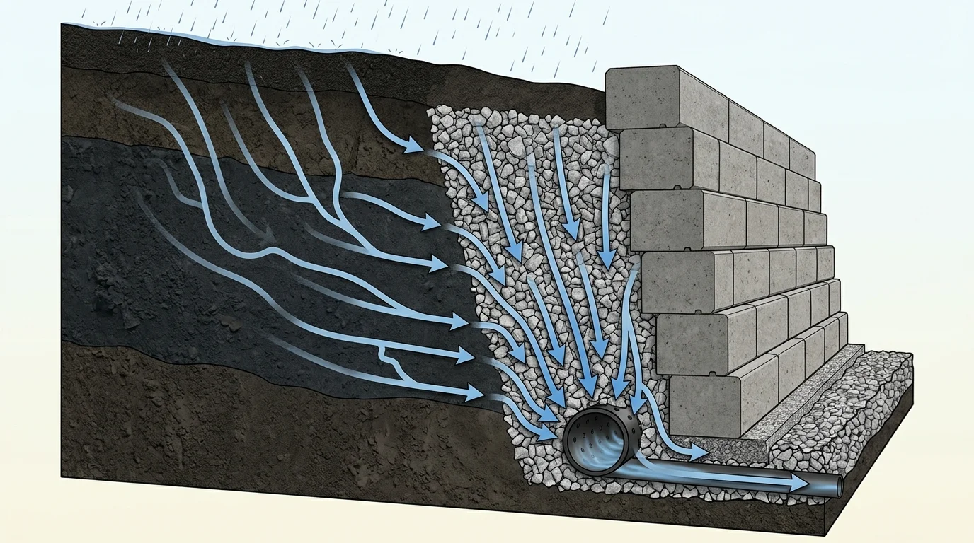
Technical illustration showing rainwater flowing through a clean crushed gravel column to a perforated pipe behind a retaining wall
Step 8: Drainage physics in action. Groundwater drops rapidly through clean crushed stone into the perforated pipe, preventing hydrostatic pressure buildup.
What Happens:

Lay a 4-inch perforated drainage pipe behind the base course on a positive slope (minimum 1% pitch) directing water toward a daylight exit. Fill the 12-inch space directly behind the blocks with clean 3/4-inch washed angular crushed stone. Place a non-woven geotextile filter fabric between this stone column and the native backfill.

Why It Matters:

Water is the primary enemy of retaining walls. The free-draining stone column allows groundwater to drop instantly to the perforated pipe, relieving destructive hydrostatic pressure before it pushes against the wall face.

What Can Go Wrong:

Omission of filter fabric allows fine silt from native soil to wash into the crushed stone, completely clogging the drainage voids within two seasons.

Critical Caution: Ensure the perforated pipe holes face downward (at the 4 and 8 o'clock positions) and that the pipe exits to daylight through a core-drilled outlet or downslope swale.
09Phase 09 of 10

Installing Geogrid Reinforcement Where Engineered

In corporate structural systems or taller walls, place horizontal geogrid layers between courses, pulled taut into the backfill.

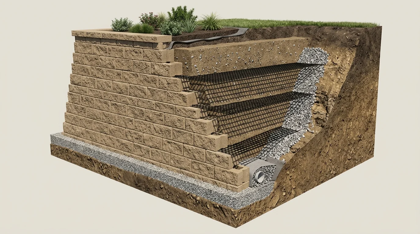
3D diagram showing geogrid reinforcement mesh layers extending backward from segmental blocks into compacted infill soil
Step 9: Mechanically Stabilized Earth (MSE). Geogrid mesh layers interlock with compacted soil, transforming the backfill into a massive anchor.
What Happens:

Where specified by manufacturer engineering tables or structural plans, lay geogrid mesh flat across the top of the block course, lock it into the alignment pins, and extend it backward into the excavated slope. Pull the grid taut and stake it in place before spreading and compacting infill backfill over it.

Why It Matters:

Geogrid locks the facing blocks to a large mass of compacted soil behind the wall, turning the soil itself into a heavy, reinforced composite structure that cannot slide or topple.

What Can Go Wrong:

Installing geogrid with the strength axis in the wrong orientation, leaving slack in the mesh, or driving heavy compaction equipment directly over bare geogrid.

Critical Caution: Follow engineered design documents for exact geogrid lengths, vertical course spacing, and tensile strength ratings. Never splice geogrid sections along the length of a run.
10Phase 10 of 10

Capping the Wall, Compacting Soil & Finishing Surface Drainage

Adhere heavy cap units with flexible concrete adhesive, compact final soil layers, and grade surface runoff away from the wall.

What Happens:

Secure universal cap stones to the top course using two continuous beads of high-strength exterior polyurethane concrete adhesive. Place an impermeable topsoil or clay cap (6 to 8 inches) over the filter fabric to prevent surface water from cascading directly into the drainage aggregate.

Why It Matters:

Cap stones protect the hollow cores and pins of lower blocks from rain and snow, while finished grading prevents lawn runoff from eroding the backfill.

What Can Go Wrong:

Using standard interior construction adhesive that degrades during winter freezes, allowing caps to slide off when walked upon.

Critical Caution: Grade the finished lawn with a gentle swale pitching water away from the wall cap. Never direct roof downspouts or sump pump discharge toward a retaining wall.

Engineering Rigor

Why the First Course Matters: Compound Geometric Error

In carpentry or drywall, small errors can often be trimmed, shimmed, or filled. In a dry-stacked segmental concrete retaining wall, there is zero tolerance for base errors:

When a base block sits just 1/16 of an inch out of level across its 12-inch width, that tilt is transferred to the block above it. Because subsequent courses sit on the tilted surface and interlock with alignment pins, the error multiplies with every layer. By course four or five, adjacent blocks will bind, gaps will open up between faces, and the wall will develop an alarming outward wave.

The Golden Rule of Base Courses:Spend 60% of your construction time on the leveling pad and first course. If block #1 takes 20 minutes of tapping and checking with a level to get 100% true in both directions, that is time well spent. Never proceed to the second course until the entire first course is completely buried, aligned, and level across every single block.

Hydraulic Physics

Why Drainage Is Part of the Structure, Not an Optional Extra

Retaining wall failures are rarely caused by defective concrete blocks. They fail because water collects behind the wall and has nowhere to go.

When rain falls on the slope above, water permeates downward through the soil. When it hits the back of a solid wall, it creates a hydraulic dam. As water fills the soil voids, lateral hydrostatic pressure spikes dramatically. In freezing New England winters, this trapped water freezes into solid ice, expanding by 9% in volume and delivering tons of outward hydraulic frost heave directly against the top three courses of blocks.

A clean 12-inch column of 3/4-inch washed crushed stone and a perforated pipe wrapped in geotextile fabric acts as a permanent pressure release valve. It prevents water from ever standing against the wall face, safeguarding your investment against seasonal frost damage.

Soil Mechanics

Backfill Material Realities & Proper Compaction

A common amateur mistake is shoving ordinary excavated topsoil or sticky clay back into the trench behind the wall. Clay expands when wet, shrinks when dry, drains poorly, and creates massive lateral pressures.

Structural backfill should consist of well-drained, granular aggregate or select clean infill soil. Crucially, backfill must be compacted in thin lifts—never more than 6 to 8 inches at a time. Placing 3 feet of loose dirt behind a wall and driving over it with a lawn tractor will result in massive post-construction settlement, dipping pavers, and cracked retaining blocks after the first autumn storm.

Caution: Operate vibratory plate compactors at least 12 inches away from the front face of the blocks to avoid pushing units outward out of plumb during compaction.

Local Climate Realities

Building Retaining Walls in Peabody & the North Shore (Zone 6b)

Homeowners in Essex County face unique geological and environmental conditions that shape how retaining walls must be planned:

New England granite fieldstone retaining wall stabilizing a wooded sloped residential property during late autumn
North Shore residential landscape: dense glacial till soils and intense freeze-thaw cycling require deep granular bases and clean aggregate drainage columns.
1. Zone 6b Freeze-Thaw Cycles

Peabody experiences repeated freeze-thaw cycles between December and March, with frost penetration reaching 36 to 48 inches into undisturbed soil. Flexible, dry-stacked segmental block systems excel here because individual courses can flex slightly without cracking, unlike rigid mortared masonry walls that heave and fracture.

2. Paxton-Charlton Glacial Till

Much of Peabody and the surrounding North Shore sits on dense basal glacial till interspersed with granite boulders, cobbles, and hardpan clay. Excavating trenches frequently uncovers large granite outcroppings or underground ledge that require heavy hydraulic excavators or jackhammers to achieve proper footing depths.

3. Groundwater Seepage on Hillsides

Neighborhoods in West Peabody, areas flanking Proctor Brook, and properties sloping toward Suntaug Lake experience seasonal groundwater tables in spring. Proper gravity daylighting of drainage pipes is critical to prevent water from pooling at the base of retaining foundations.

4. Winter Deicing Salt Exposure

If a retaining wall borders a residential driveway or street, winter road salt and deicing chemicals will wash against the face. Specifying high-density, freeze-thaw tested concrete units (conforming to ASTM C1372 specifications for segmental retaining wall units) ensures long-term resistance to salt spalling.

Material Selection

Retaining Wall Materials: Comparing Costs, Durability & Complexity

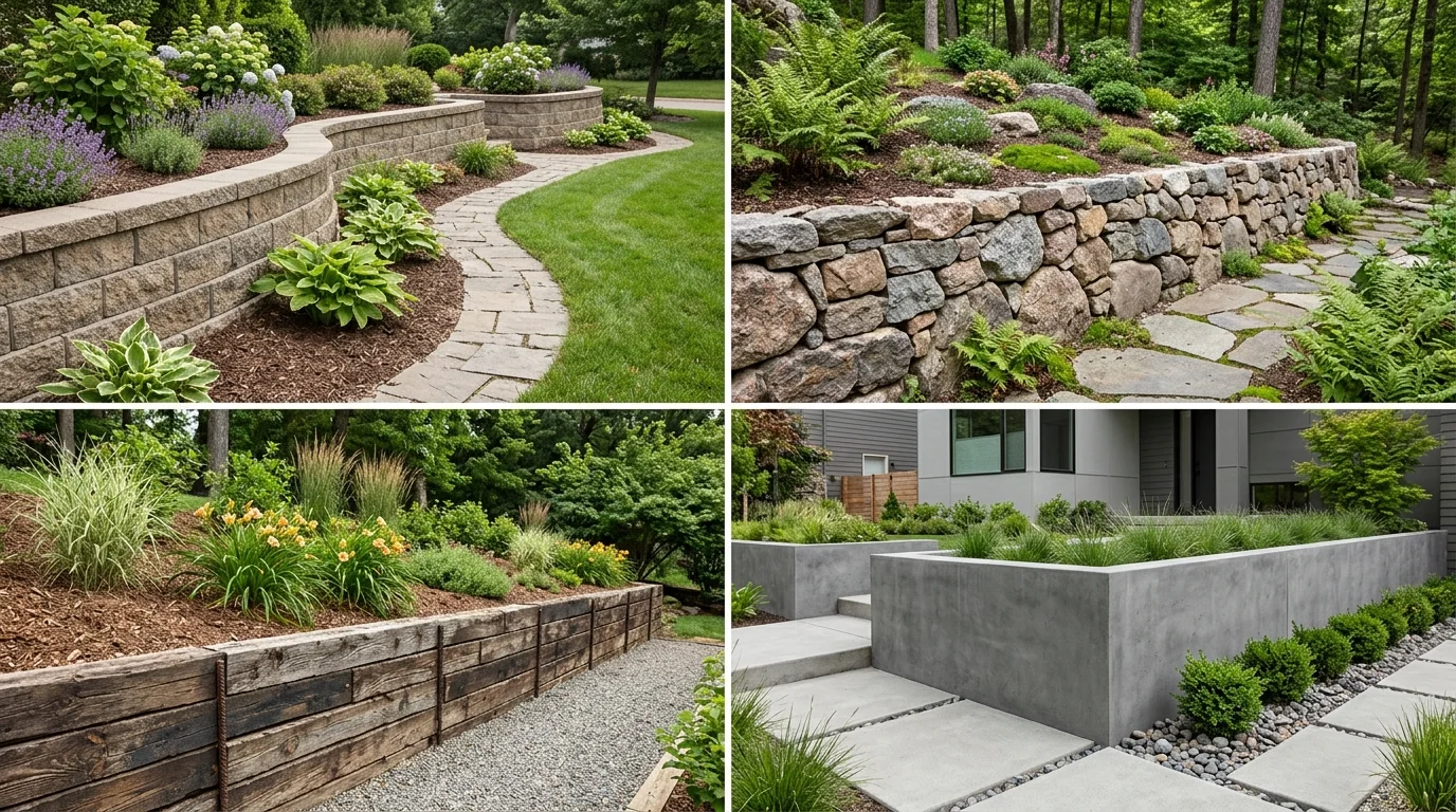
Comparison of four residential retaining wall materials: segmental block, natural granite fieldstone, timber ties, and poured concrete
Four distinct retaining wall styles: modular segmental block (top left), dry-stack natural fieldstone (top right), landscape timbers (bottom left), and poured reinforced concrete (bottom right).
Wall SystemAppearance & StyleIdeal ApplicationDurability & LifeDIY FeasibilityEngineering Trigger
Segmental Concrete Blocks (SRW)Engineered split-face, tumbled, or smooth modular textures in earth tones.Residential garden terraces, slope stabilization, driveway cut retention.Exceptional (50+ years); manufactured to 3,000–5,000+ psi; freeze-thaw resistant.Moderate (units weigh 25–85 lbs; requires precise leveling and trenching).Exceeding 4 ft total height or supporting any slope or vehicular surcharge.
Dry-Stack Natural Fieldstone / GraniteRustic, organic, historic New England stonework with natural crevices.Low garden borders (<3 ft), historic property boundaries, informal terraces.Centuries; unmortared joints flex with frost and weep water naturally.High (requires skilled eye for stone shaping, chinking, and center gravity).Walls over 3 ft, poor soil stability, or surcharge placement.
Mortared Natural Stone MasonryFormal, tight-jointed, elegant stone masonry with finished mortar joints.Formal estate entryways, raised terraces, front architectural walls.High, but rigid; vulnerable to cracking if footing moves during frost heaves.Very High (requires reinforced concrete footing below 48-inch frost line).Mandatory structural engineering and building permits in Massachusetts.
Poured Reinforced ConcreteMonolithic, industrial, clean architectural face (can receive stone veneer).Deep commercial cuts, extreme slope stabilization, tight property boundaries.Exceptional strength; requires proper water drainage to prevent spalling.Extreme (requires formwork, steel rebar tie-ins, and ready-mix trucks).Mandatory structural engineering and municipal building permits.
Treated Landscape Timbers / Railroad TiesRustic, linear wood aesthetic with stained or natural timber look.Budget-conscious low garden terraces, raised planting beds.Limited (10–20 years); susceptible to ground rot, termites, and wood warping.Moderate (lighter to carry, but requires steel rebar pins and deadmen anchors).Not recommended for structural retaining walls exceeding 3 feet.

Decision Support

DIY vs. Independent Professional: Objective Decision Framework

Building a retaining wall is physically punishing and structurally unforgiving. Use this objective checklist to evaluate whether your project is a feasible DIY undertaking or requires professional equipment and engineering.

Feasible DIY Projects

Low-risk landscape improvements where structural failure presents minimal danger:

  • Wall height under 3 feet: Measured from the bottom of the trench to the capstone.
  • Level ground above and below: No steep slopes pitching down toward the wall.
  • Zero surcharges: No driveways, parked cars, hot tubs, or adjacent buildings within a 45° line of influence.
  • Clear, accessible site: Sandy-loam soil that can be hand-dug without heavy excavators or rock saws.

Hire an Independent Professional

High-stakes structural projects requiring heavy machinery and engineering:

  • Total height exceeds 4 feet: Triggers 780 CMR building permits and PE engineered stamped plans.
  • Driveway or structural surcharge: Any vehicular parking or building foundation located behind the wall.
  • Tiered or multi-level walls: Lower walls supporting the load of upper terraces require global stability calculations.
  • Heavy glacial till or ledge: Massive rocks requiring hydraulic mini-excavators with pneumatic breakers.

Failure Prevention

Why Retaining Walls Lean or Fail: Common Construction Mistakes

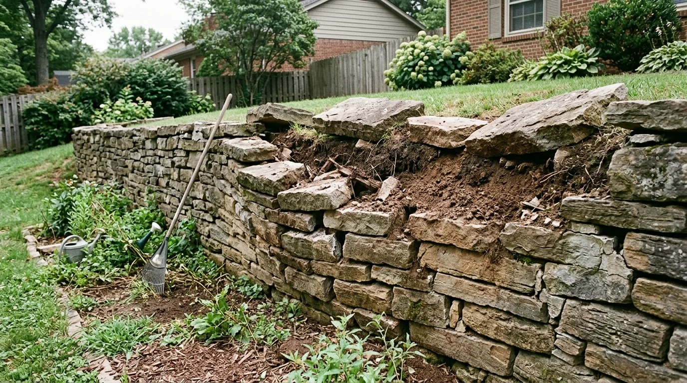
Failing residential retaining wall showing severe outward bulge, forward leaning, displaced stones, and eroded backfill
Signs of structural retaining wall failure: outward bulging, forward tilt, loss of backfill, and collapsed capping. Retaining walls that have failed cannot be pushed back—they must be dismantled and rebuilt with engineered drainage.
1. Omission of Drainage Gravel

Backfilling directly against the blocks with native soil traps rainwater. The hydrostatic pressure forces the wall outward, resulting in the classic "belly bulge" along the midsection.

2. Inadequate Base Burial (Shallow Toe)

Placing the first course on top of the ground without burying it leaves the bottom blocks vulnerable to sliding forward (toe kick-out) under lateral soil pressure.

3. Missing Geotextile Fabric

Using crushed stone drainage without wrapping it in filter fabric allows fine clay and silt to migrate into the gravel voids, choking drainage within 2 to 3 rainy seasons.

4. Uncompacted Backfill Lifts

Dumping 2 feet of dirt into the trench without mechanical compaction leaves vast voids that settle over time, creating surface sinkholes and tipping the wall backward or forward.

5. Ignoring Surcharge Loads

Building a standard gravity wall within 3 feet of a driveway or parking area without geogrid reinforcement leads to rapid structural failure under vehicle axle weights.

6. No Outlet for the Drain Pipe

Installing a perforated pipe that doesn't exit to daylight turns the pipe into a buried underground reservoir, holding water directly against the foundation pad.

Important Structural Diagnostic Warning:

If your existing retaining wall is visibly leaning forward, bulging outward, or showing sheared cracked blocks, do not attempt cosmetic repairs or mortar patches. A leaning wall cannot simply be pushed back into place. Significant movement indicates foundation failure or hydrostatic buildup that requires an on-site evaluation by an experienced hardscaping contractor or structural engineer.

2026 Budgeting

Retaining Wall Cost Expectations & Project Drivers

Retaining wall costs in Massachusetts are calculated primarily by the face square foot (length of wall × exposed height). In eastern Massachusetts and the North Shore, typical planning benchmarks include:

Segmental Concrete Blocks (SRW)

$25 – $45 / face sq ft

Includes excavation, base aggregate, modular precast blocks, drainage gravel, perforated pipe, filter fabric, and mechanical backfill compaction.

Natural Split-Face Granite or Fieldstone

$35 – $75+ / face sq ft

Reflects the higher material cost of quarried New England stone and the extensive hand-chiseling labor required to fit individual irregular units.

Primary Cost Drivers on Your Property:

  • Machine Accessibility: Tight backyards requiring manual wheelbarrows instead of skid-steers increase labor costs by 20% to 35%.
  • Excavation into Glacial Ledge: Encountering granite bedrock in West Peabody requires hydraulic rock hammers, moving bids into higher contingency brackets.
  • Height & Geogrid Requirements: Walls exceeding 4 feet require additional excavation depth, geogrid reinforcement rolls, and municipal permit fees.
  • Integrated Steps & Corners: Building 90° corners, curved radius returns, and integrated stone staircases adds cutting and fitting labor.

For a detailed analysis across all residential hardscape and softscape improvements, explore our comprehensive Peabody landscaping cost guide.

Regional cost benchmarks synthesized from HomeGuide, Angi eastern Massachusetts contractor surveys, and North Shore material supplier pricing.

Homeowner Answers

Frequently Asked Questions About Building Retaining Walls

Answers

Frequently asked questions

01

How does a retaining wall differ from a garden border?

A decorative garden border simply separates lawn from mulch or planting beds without holding back elevated earth. A retaining wall is an engineered structural system designed to resist active lateral earth pressure, soil weight, and hydrostatic water pressure from an elevated ground grade behind it.

Compare decorative flower bed edging borders →

02

When does a retaining wall require a building permit in Massachusetts?

Under the Massachusetts State Building Code (780 CMR, 10th Edition), a building permit is generally required for any retaining wall retaining more than 4 feet (1,219 mm) of unbalanced fill, measured from the bottom of the footing or leveling pad to the top of the wall. Additionally, ANY retaining wall supporting a surcharge—such as a driveway, parking pad, building foundation, swimming pool, or steep uphill slope—requires a building permit and stamped engineering plans from a licensed Professional Engineer (PE), regardless of height.

Learn about professional retaining wall installations in Peabody →

03

Why is drainage considered part of the retaining wall structure?

Trapped groundwater generates hydrostatic pressure against the back of retaining blocks, which can double or triple the horizontal force pushing against the wall. Without a dedicated column of clean crushed stone (typically 12 inches minimum) and a perforated drain pipe sloped to gravity daylight, trapped water will inevitably cause the wall to bulge, tilt forward, or heave during winter freeze-thaw cycles.

Explore residential yard drainage solutions →

04

Why is leveling the first course of blocks so critical?

In a segmental retaining wall system, any microscopic error in the first course—even a 1/16-inch tilt or height variance—compounds geometrically with each subsequent layer. By the third or fourth course, that slight imperfection results in visible waviness, misaligned interlocking setback lips, uneven joint gaps, and localized structural instability.

05

Can I use excavated yard soil directly behind a retaining wall?

No. Ordinary native yard soil—especially dense clay, silt, or rocky glacial till common across Essex County—holds water, drains poorly, and exerts massive hydrostatic pressure when wet. The immediate 12-inch zone directly behind retaining blocks must be filled with clean, free-draining angular crushed aggregate (such as 3/4-inch crushed stone) separated from native backfill by non-woven filter fabric.

06

What is geogrid and when is it required?

Geogrid is a high-tensile flexible polymer mesh installed horizontally between courses of retaining blocks, extending several feet backward into the backfill soil. It interlocks with compacted aggregate to turn the soil mass behind the wall into a unified, reinforced composite structure (Mechanically Stabilized Earth). Geogrid requirements depend on manufacturer engineering tables, wall height, soil friction angles, and slope or surcharge loads.

07

How much does it cost to build a retaining wall in Massachusetts?

In eastern Massachusetts, professional segmental concrete block retaining wall installations typically average $25 to $45 per square foot of exposed wall face, while natural split-face granite or quarried stone ranges from $35 to $75+ per square foot. Project totals vary based on excavation depth into rocky glacial till, machine access, geogrid reinforcement, and municipal permitting.

Review regional Massachusetts landscaping cost benchmarks →

Updated:

Planning a Retaining Wall Project in Peabody or the North Shore?

Call Now

Get connected with an independent local landscaping professional. Calls go to (877) 537-6896.

Peabody & North Shore

Talk to a local pro

Call Now